Friday, 5 February 2016

The Universe

          The Universe has no edge and nothing exists beyond it, not even space. In the vastness of the Universe, the Earth, the Sun and planets are tiny dots. The Sun is merely one star in a galaxy comprising 100,000 million stars. At least as many thousands of million of other galaxies, each with its own star system, extend as far as the largest and most sophisticated of optical and radio telescopes can reach.

          As the Universe expands, all galaxies and clusters of galaxies move apart from each other at speeds that depend upon their distances. The each other at speeds that depend upon their distances. The furthest ordinary galaxy yet detected, Abell 1835 IR is 13,230 million light years away and is receding at 45 per cent of the speed of light. The most distant object in the Universe as on 14 July 2004 is in background of Abell 2218. This corresponds to a distance greater than 2 billion light years. Beyond this, astronomers are looking back to a time when the Universe was born, and the detectable Universe fades out.

          Our present view of universe began with the findings of Copernicus, Galileo, and Newton. What they found was very much opposed by others at the time, mainly because established order was based on Aristotle's teachings. These "new" ideas were thought to diminish the role of humans in the universe, to undermine our importance we have expanded our vision since then by enormous effort, painstaking observations, and an ongoing desire to comprehend our surroundings.

Universe theory:

The Big Bang Theory:
          According to this theory, the Universe had its origin in a giant explosion about 18,000 million years ago. The Matter flung out from the explosion condensed into lumps called galaxies, which are still rushing outwards. As the Universe grows old, the matter in it thins out. The expansion continues indefinitely. The Big Bang theory received its strongest confirmation when 'cosmic background radiation' was discovered in 1964 by Amo Penzias and Robert Wilson, who won the Nobel Prize for this discovery. In 2003, NASA's Wilkinson Microwave Antisotropy Probe made measurements of the temperature of this 'cosmic microwave background' radiation to within millionth of a degree. From these measurements scientists were able to deduce that our universe is 13.7 billion years old and that first generation stars began to form a mere 200 million years after the Big Bang.  

Inflation Theory:
          Immediately following the Big Bang, the universe likely began a period of exaggerated outward expansion, with matter flying outward faster than the current speed of light. This is the inflation theory, widely accepted in the astrophysics community.

The Oscillating Universe Theory:
          This theory, a variation of the Big Bang Theory, suggests that expansion of the Universe will eventually slow down and stop, followed by contraction of the galaxies into another Big Bang. The Universe, therefore, continues in endless cycles of expansion and contraction; the laws of nature may differ in each cycle.

The Steady State Theory:
          An alternative view to the Big Bang Theory, this theory says that Universe never originated at any one instant, nor will it ever die. According to this theory, as the Universe expands new matter is created to fill the space left. Therefore, the appearance of the Universe remains constant with time.


Thursday, 4 February 2016

Robotic Arc Welding System (RAWS)


     Arc welding and GMAW/GTAW welding processes are at present the major fabrication techniques in most of the industries, world over. Best results are achieved by automating the process, using robots and microprocessor controlled systems. Mechanisation and automation of arc welding techniques results in consistent quality joints. It has now become indispensable where high rates of production are involved and for welding in inaccessible/hazardous environment because the robots can be inverted, suspended over a welding station or supported in any unusual position. It also overcomes labour fatigue and results in overall economy, higher productivity and improved working conditions.

     Where welding of linear, circular or spiral joints is involved, mechanisation of arc welding process is good enough. However, for compex joints not accessible freely, automation of the process using robots is belter suited. Robotic arc welding system (RAWS) is best suited for batch production involving frequent design changes in a component and even where different components are to be handled one after other. This is possible due to the highly flexible system provided by RAWS. However the justification for installation of such a system has to be looked through return on investment by considering all the expenses (on equipment, material handling devices, training, etc.) and the likely savings on account of increased production, improved quality, saving of energy, men-hours and materials due to reduction in reworking of components, lower turn-over of employees in the shop and reduced burden of strikes, etc.


     Fig  shows a schematic arrangement of robotic arc welding system (RAWS) and the various units involved. The robot consists of manipulator (series of mechanical linkages and joints capable of producing all sorts of designed movements), controller and power supply unit (to provide energy to the activators). Each link of manipulator is driven by activators which may be operated either, by hydraulic/pneumatic power cylinder or electrical motor. The forearm of robot can move in a nearly spherical way, thus covering a large working volume and providing greater application flexibility. It is easily possible to reach down into or onto objects placed over the conveyor. Feedback devices are incorporated to sense the positions of the various links and joints. The information from these devices is fed to the controller. The controller initiates and terminates motions of the manipulator in desired sequences and at desired points through interfaces with and manipulator's activators and feedback devices. It also stores position and sequence data in memory and performs complex arithmetic functions to control path, speed and position. The controller is also lined with other auxiliary devices like power source, wire feed unit, conveyor etc.
The control unit has a computer with lot of computational capability. The movement of torch centre point installed at the end of forearm of robot can be controlled either by

(i) co-ordinated axis control motions, or
(ii) controlled path generation.

     Only the end points in case of linear path land three points in case of circular path are specified and the computer automatically generates the controlled path at the desired velocity including acceleration and retardation.

     An important feature of the RAWS is the searching and following of the actual welding seam or groove/ seam tracking in deviation of the pre-planned line. Without this facility, the programmed welding groove and actual welding groove would be different because of errors due to imprecise component clamping and assembly of improper fit-up and inconsistent orientation of the component, etc. However seam tracking system takes care of these problems and ensures the actual welding grooves to be as per programmed welding grooves.

     In the Case of multi-run welding process, the first (root) pass is welded by using seam tracking and the various off-set displacement are stored in the memory. For subsequent passes, seam tracking is not required because the processor shifts the programmed path data of the obtained correct location for the given set up.

     An oscillation movement of torch is required for bridging of the gaps and for welding in difficult positions. The control unit can provide the oscillation movement with programmable frequency and amplitude for the given requirements.
The control unit also incorporates facilities like axes transformation (for welding similar work pieces at different stations by changing the positions of a set programme with regard to one or several coordinates), mirror imaging (welding identical jobs but from opposite sides of a manufacturing line), random access reserve function (to allow welding job to be carried out in any sequence on a number of working stations), etc. For high positional accuracy of the torch typically ≡ 0.2 mm), the arms around the rotating axis should be balanced, employing needle bearings and using feedback sensing systems having high resolving power.

     For consistent welding operations and weld quality, the torch angle with respect to the work is kept constant by employing gyroax is mechanism, etc.

In case of emergency, the system comes to a halt. The control panel has all the facilities for position status and failure displays. The system incorporates built in diagnostic facilities. Sometimes, a backup system is provided to avoid loss of production in case of breakdown of RAWS.
     
     The operations to be performed by the robot should be within its capacity, such as carrying load, work envelope, speed and complexity. To minimise the down time, it is essential that a team of trained personnel to operate and maintain the system along with adequate tools and spare parts is available.


Wednesday, 3 February 2016

Automatic Welding Process


          Automation, like in other fields, in welding too, increases production, improves quality and lowers cost. Automatic welding employs various automatic power devices (variable speed drive motors), gas controls, coolant fluid, controls, sequence controls, instruments, gauges, timers, limit switches, etc.

Some of the advantages and limitations of automating arc-welding are listed below.

Advantages:
           High weld rate; uniform weld height, width, fusion and penetration ; low electrode stub loss due to the continuous feed from a reel of welding wire; use of high currents; automatic care of arc length, speed and other variables to produce quality weld.

Limitations:
           Correctly fitting weldment components have to be used to obtain all the advantages, no compensation (in form of speed control) for poor fits and alignments is possible, once the automatic controls have been adjusted.
The various components involved in automatic welding are described briefly below :

Adjustable speed drive motors:
          These are used to move the torch/electrode along the work at a controlled rate, and to feed the welding wire from coils into the weld area. In arc welding the adjustment of arc length is important to obtain quality welds. Change in arc length due to poor fits, etc. is sensed by the voltage changes in the welding transformer and a signal is sent to wire drive motor to speed up if voltage rises and vice versa. The best motor for such cases is the low voltage series wound universal motor whose speed varies proportionally to the voltage. These motors are then electrically connected to the arc circuit so that as arc length increases, voltage in the arc circuit increases which automatically increases the feed rate to adjust the arc length. Manual'override controls to feed wire are also provided.

Gas Controls:
           Gas is used in gas welding and in inert gas arc welding. These consist of pressure regulators, flow meters, and solenoid valves for gas flow control. The solenoid valve may bq energizing by pressing a push button, or automatically as follows. When arc is struck, current flows in the secondary winding which can be used to energizing a relay, which in turn energizing a solenoid. Since gas flow is required for a short time on breaking of arc in order to protect the electrode from contamination during cooling, a bimetal strip is utilized to de-energisc the solenoid valve on gas line with time delay. As long as gas arc is on, current through secondary windings also keeps solenoid energizing. When arc is broken, current in secondary winding falls to zero, but bimetal strip takes time in cooling and changing its position. Thus solenoid valve remains open for some extra time on breaking of arc.

Water controls:
           Some coolant (usually water) is required for cooling transformers, electrodes (in resistance welding), and electrode holders (in GTAW and GMAW welding). The pressure and flow oil cooling medium must be properly controlled to reduce wear and increase efficiency of welding. Interlocks to stop welding machine in case of inadequate coolant supply are provided. The solenoid valve in coolant supply line is energizing  only when welding is “on” by energizing it through the current in the secondary circuit.

         Three- way solenoid valves are used to direct the hydraulic pressure to be communicated to either operate a cylinder to perform certain operation or to reservoir of oil.

        The operation phases of a welding cycle arc controlled by timers which may be mechanical type (cam or clock) or electronic type. Sometimes exact timings have to be controlled as in the case of spot welding of aluminium or stainless steel. This can be done by thyratr on controls in conjunction with ignition controls which permit up to 1500 interruptions per minute. It is possible to control current flow in welding operation to produce regulated amount of heat by phase shifting the AC cycle. Sometimes sequence controls are utilized to stagger starting operation of various welding machines in a shop to reduce the instantaneous heat load on AC supply lines. Sufficient instrumentation is provided in automatic welding operation to monitor working of various electrical, electronic, cooling, pneumatic and hydraulic circuits. Parameters like weld pressure, forge pressure weld current, weld time and forge time are monitored and recorded on a recorder for permanent records. It has been possible to fully automate practically all welding processes, viz. gas welding, arc welding, resistance welding, brazing, cutting, metal surfacing etc.

      It may be understood that automatic welding calls for more safety precautions than manual welding. It should be thoroughly ensured before starting automatic operation that various movements are without any obstruction and hindrances and that various devices during their operation do not move in hazardous area.


Sunday, 3 January 2016

Universal Surface Gauge

     This is a most versatile instrument used in non-precision measurements. It is generally used with surface plate for layout work and inspection. It consists of a rigid base whose bottom surface is made perfectly flat. A spindle carrying a scriber in a universal clamp is attached to the base. The spindle can be inclined to the base in any position and clamped in place by tightening the spindle nut. After tightening it, slight inclination can be further given for finer adjustments by an adjusting screw. Actually the turning of the adjusting screw moves the whole spindle assembly up or down thereby tilting it very slightly. The scriber can by slid up or down the spindle and at the same time tipped back or forth in any position. The scriber can thus be set at any position desired. The base of the universal surface gauge is generally grooved so that it may be used on cylindrical surfaces also. Two pins are also placed in the base to serve as guides when scribing from the edge of the surface plate

     To set a universal surface gauge to a particular dimension, use can be made of a steel rule positioned at 90 degree to the datum with the help of angle plate and then lines can be scribed on the workpiece.

     Many a time surface gauge is very successfully used for centring the work at lathe. It is capable of precision measurements also when used in conjunction with dial indicator.

Thursday, 25 June 2015

Keyboard Shortcuts (Microsoft Windows)

1. CTRL+C - (Copy)
2. CTRL+X - (Cut)
3. CTRL+V-  (Paste)
4. CTRL+Z - (Undo)
5. DELETE - (Delete)
6. SHIFT+DELETE - (Delete the selected item permanently without placing the item in the Recycle Bin)
7. CTRL while dragging an item - (Copy the selected item)
8. CTRL+SHIFT while dragging an item - (Create a shortcut to the selected item)
9. F2 key - (Rename the selected item)
10. CTRL+RIGHT ARROW - (Move the insertion point to the beginning of the next word)
11. CTRL+LEFT ARROW-  (Move the insertion point to the beginning of the previous word)
12. CTRL+DOWN ARROW - (Move the insertion point to the beginning of the next paragraph)
13. CTRL+UP ARROW - (Move the insertion point to the beginning of the previous paragraph)
14. CTRL+SHIFT with any of the arrow keys - (Highlight a block of text)
15. CTRL+A -  (Select all)
16. F3 key - (Search for a file or a folder)
17. ALT+ENTER - (View the properties for the selected item)
18. ALT+F4 - (Close the active item, or quit the active program)
19. ALT+ENTER - (Display the properties of the selected object)
20. ALT+SPACE BAR - (Open the shortcut menu for the active window)
21. CTRL+F4 - (Close the active document in programs that enable you to have multiple documents open simultaneously)
22. ALT+TAB - (Switch between the open items)
23. ALT+ESC - (Cycle through items in the order that they had been opened)
24. F6 key - (Cycle through the screen elements in a window or on the desktop)
25. F4 key - (Display the Address bar list in My Computer or Windows Explorer)
26. SHIFT+F10 - (Display the shortcut menu for the selected item)
27. ALT+SPACE BAR - (Display the System menu for the active window)
28. CTRL+ESC - (Display the Start menu)
29. ALT+Underlined letter in a menu name - (Display the corresponding menu) Underlined letter in a command name on an open menu (Perform the corresponding command)
30. F10 key - (Activate the menu bar in the active program)
31. RIGHT ARROW - (Open the next menu to the right, or open a sub menu)
32. LEFT ARROW - (Open the next menu to the left, or close a sub menu)
33. F5 key - (Update the active window)
34. BACKSPACE  - (View the folder one level up in My Computer or Windows Explorer)
35. ESC - (Cancel the current task)
36. SHIFT when you insert a CD-ROMinto the CD-ROM drive - (Prevent the CD-ROM from automatically playing)

Tuesday, 19 May 2015

AFBC / Bubbling Bed Boiler

Atmospheric classic Fluidised Bed Combustion System AFBC / Bubbling Bed:
            In AFBC, coal is crushed to a size of 1 – 10 mm depending on the rank of coal, type of fuel feed and fed into the combustion chamber. The atmospheric air, which acts as both the fluidization air and combustion air, is delivered at a pressure and flows through the bed after being preheated by the exhaust flue gases. The velocity of fluidising air is in the range of 1.2 to 3.7 m /sec. The rate at which air is blown through the bed determines the amount of fuel that can be reacted.
            Almost all AFBC/ bubbling bed boilers use in-bed evaporator tubes in the bed of limestone, sand and fuel for extracting the heat from the bed to maintain the bed temperature. The bed depth is usually 0.9 m to 1.5 m deep and the pressure drop averages about 1 inch of water per inch of bed depth. Very little material leaves the bubbling bed – only about 2 to 4 kg of solids are recycled per   ton of fuel burned. Typical fluidised bed combustors of this type are shown in Fig - 1 and fig -2.


            The combustion gases pass over the super heater sections of the boiler, flow past the economizer, the dust collectors and the air pre heaters before being exhausted to atmosphere.

            The main special feature of atmospheric fluidised bed combustion is the constraint imposed by the relatively narrow temperature range within which the bed must be operated. With coal, there is risk of clinker formation in the bed if the temperature exceeds 950°C and loss of combustion efficiency if the temperature falls below 800°C. For efficient sulphur retention, the temperature should be in the range of 800°C to 850°C.
General Arrangements of AFBC Boiler
AFBC boilers comprise of following systems:
i) Fuel feeding system
ii) Air Distributor
iii) Bed & In-bed heat transfer surface
iv) Ash handling system.
Many of these are common to all types of FBC boilers.
1. Fuel Feeding System:
For feeding fuel, sorbents like limestone or dolomite, usually two methods are followed: under bed pneumatic feeding and over-bed feeding.
Under Bed Pneumatic Feeding
If the fuel is coal, it is crushed to 1–6 mm size and pneumatically transported from feed hopper to the combustor through a feed pipe piercing the distributor. Based on the capacity of the boiler, the number of feed points is increased, as it is necessary to distribute the fuel into the bed uniformly.
Over-Bed Feeding
The crushed coal, 6–10 mm size is conveyed from coal bunker to a spreader by a screw conveyor. The spreader distributes the coal over the surface of the bed uniformly. This type of fuel feeding system accepts over size fuel also and eliminates transport lines, when compared to under-bed feeding system.
2. Air Distributor:
The purpose of the distributor is to introduce the fluidizing air evenly through the bed cross section thereby keeping the solid particles in constant motion, and preventing the formation of defluidization zones within the bed. The distributor, which forms the furnace floor, is normally constructed from metal plate with a number of perforations in a definite geometric pattern. The perforations may be located in simple nozzles or nozzles with bubble caps, which serve to prevent solid particles from flowing back into the space below the distributor.
The distributor plate is protected from high temperature of the furnace by:
i) Refractory Lining
ii) A Static Layer of the Bed Material or
iii) Water Cooled Tubes.
3. Bed & In-Bed Heat Transfer Surface:
a) Bed
The bed material can be sand, ash, crushed refractory or limestone, with an average size of about 1 mm. Depending on the bed height these are of two types: shallow bed and deep bed. At the same fluidizing velocity, the two ends fluidise differently, thus affecting the heat transfer to an immersed heat transfer surfaces. A shallow bed offers a lower bed resistance and hence a lower pressure drop and lower fan power consumption. In the case of deep bed, the pressure drop is more and this increases the effective gas velocity and also the fan power.
b) In-Bed Heat Transfer Surface
In a fluidised in-bed heat transfer process, it is necessary to transfer heat between the bed material and an immersed surface, which could be that of a tube bundle, or a coil. The heat exchanger orientation can be horizontal, vertical or inclined. From a pressure drop point of view, a horizontal bundle in a shallow bed is more attractive than a vertical bundle in a deep bed. Also, the heat transfer in the bed depends on number of parameters like (i) bed pressure (ii) bed temperature (iii) superficial gas velocity (iv) particle size (v) Heat exchanger design and (vi) gas distributor plate design.
4. Ash Handling System:
a) Bottom Ash Removal
In the FBC boilers, the bottom ash constitutes roughly 30 – 40 % of the total ash, the rest being the fly ash. The bed ash is removed by continuous over flow to maintain bed height
and also by intermittent flow from the bottom to remove over size particles, avoid accumulation and consequent defluidization. While firing high ash coal such as washery rejects, the bed ash overflow drain quantity is considerable so special care has to be taken.
b) Fly Ash Removal
            The amount of fly ash to be handled in FBC boiler is relatively very high, when compared to conventional boilers. This is due to elutriation of particles at high velocities. Fly ash carried away by the flue gas is removed in number of stages; firstly in convection section, then from the bottom of air preheater/economizer and finally a major portion is removed in dust collectors.

            The types of dust collectors used are cyclone, bagfilters, electrostatic precipitators (ESP’s) or some combination of all of these. To increase the combustion efficiency, recycling of fly ash is practiced in some of the units.
Features of bubbling bed boiler:
Fluidised bed boiler can operate at near atmospheric or elevated pressure and have these essential features:
• Distribution plate through which air is blown for fluidizing.
• Immersed steam-raising or water heating tubes which extract heat directly from the bed.
• Tubes above the bed which extract heat from hot combustion gas before it enters the flue duct.

Friday, 17 April 2015

gambit tutorial ( lesson-1)

CREATING AND MESHING BASIC GEOMETRY :
This tutorial illustrates geometry creation and mesh generation for a simple geometry using GAMBIT.
In this tutorial you will learn how to:
  • Start GAMBIT
  • Use the Operation tool pad
  • Create a brick and an elliptical cylinder
  • Unite two volumes
  • Manipulate the display of your model
  • Mesh a volume
  • Examine the quality of the mesh
  • Save the session and exit GAMBIT

Prerequisites:
This tutorial assumes you have no prior experience of working with GAMBIT. You should, however, read Chapter 0, "Using This Tutorial Guide," to familiarize yourself with the GAMBIT interface and with conventions used in the tutorial instructions.

Problem Description:
The model consists of an intersecting brick and elliptical cylinder. The basic geometry is shown schematically in Figure 1-1.

Figure 1-1: Problem specification
 Strategy:
This first tutorial illustrates some of the basic operations for generating a mesh using GAMBIT. In particular, it demonstrates:
  • How to build the geometry easily using the "top-down" solid modeling approach
  • How to create a hexahedral mesh automatically
The "top-down" approach means that you will construct the geometry by creating volumes (bricks, cylinders, etc.) and then manipulating them through Boolean operations (unite, subtract, etc.). In this way, you can quickly build complicated shapes without first creating the underlying vertices, edges, and faces.
Once you have built a valid geometry model, you can directly and (in many cases) automatically create the mesh. In this example, the Cooper meshing algorithm is used to automatically create an unstructured, hexahedral mesh. More complicated geometries may require some manual decomposition before you can create the mesh; this is demonstrated in subsequent tutorials.
The steps you will follow in this tutorial are listed below:
  • Create two volumes (a brick and an elliptical cylinder).
  • Unite the two volumes.
  • Automatically generate the mesh.
  • Examine the quality of the resulting mesh.
To keep this introductory tutorial short and simple, certain steps that you would normally follow have been omitted:
  • Adjusting the distribution of nodes on individual edges of the geometry
  • Setting continuum types (for example, identifying which mesh zones are fluid and which are solid) and boundary types
These details, as well as others, are covered in subsequent tutorials.

Procedure:
Type
gambit -id mechanicalmines
to start GAMBIT.
This command opens the GAMBIT graphical user interface (GUI). (See Figure 1-2.) GAMBIT uses the name you specify (in this example, mechanicalmines) as a prefix to all files it creates: for example,mechanicalmines.jou.

Figure 1-2: The GAMBIT graphical user interface (GUI)

Step 1: Create a Brick:

1. Create a brick by doing the following:
a) In the Operation tool pad (located in the top right corner of the GAMBIT GUI), select the GEOMETRY command button by clicking on it with the left mouse button. If the Geometry sub pad does not appear when you select the GEOMETRY command button, click it again.

The name of a command button is displayed in the Description window at the bottom of the GAMBIT GUI when you hold the mouse cursor over the command button. The GEOMETRY command button will appear depressed when it is selected. Selecting the GEOMETRY command button opens the Geometry sub pad. Note that when you first start GAMBIT, the GEOMETRY command button is selected by default.
b) Use the left mouse button to select the VOLUMEcommand button in the Geometry sub pad.
Again, this command button will be depressed when selected. Selecting this command button opens the Geometry/Volume sub pad.
c) Use the left mouse button to select the CREATE VOLUMEcommand button in the Geometry/Volume sub pad.
This command sequence opens the Create Real Brick form.

The above description of selecting command buttons can be shortened to the following:
GEOMETRY—> VOLUME—> 
CREATE VOLUME 
The selection of the command buttons will be represented using this method for the remainder of this tutorial, and in all subsequent tutorials.
d) Left-click in the text entry box to the right of Width in the Create Real Brick form, and enter a value of 10 for the Width of the brick.
e) Use the Tab key on the keyboard to move to the Depth text entry box, and enter 6 for the Depth of the brick.
The text entry box for Height can be left blank; GAMBIT will set this value to be the same value as the Width by default.
f) Select Centered from the option menu to the right of Direction.
NOTE: When you first open the Create Real Brick form, the Centered option is selected by default.
i) Hold down the left mouse button on the option button to the right of Direction until the option menu appears.
ii) Select Centered from the list.
g) Click Apply.
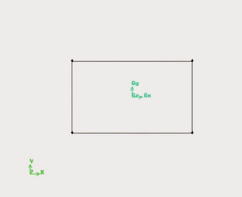
A message appears in the Transcript window at the bottom left of the GAMBIT GUI to indicate that a volume, called volume.1, was created. The volume will be visible in the graphics window, as shown in Figure 1-3.
If you make a mistake at any point in the geometry creation process, you can use the UNDO command buttonto undo multiple levels of geometry creation. At this point, you have only performed one operation, so you can only undo one operation.

Figure 1-3: Rectangular brick volume (side view)

Step 2: Create an Elliptical Cylinder:

1. Create an elliptical cylinder.
a) Hold down the right mouse button while the cursor is on the CREATE VOLUME command button.
b) Select the CREATE REAL CYLINDER optionfrom the resulting menu.
! CREATE REAL CYLINDER is the text that is written in the Description window when you hold the mouse cursor over themenu item.
This action opens the Create Real Cylinder form.

The above method of selecting command buttons can be shortened to the following:
GEOMETRY—> VOLUME—> CREATE VOLUMER
where R indicates a tool pad choice using the right mouse button.
c) Enter a Height of 10.
d) Enter a value of 3 for Radius 1.
e) Enter a value of 6 for Radius 2.
f) Retain the default Axis Location of Positive Z.
g) Click Apply.
The brick and elliptical cylinder are shown in Figure 1-4.

Figure 1-4: Brick and elliptical cylinder


Step 3: Unite the Two Volumes :

1. Unite the brick and elliptical cylinder into one volume.
GEOMETRY—> VOLUME—> BOOLEAN OPERATIONS 
This command sequence opens the Unite Real Volumes form.

Notice that the top Volumes list box is yellow in the Unite Real Volumes form at this point. The yellow colour indicates that this field is active, and any volume selected will be entered into this box on the form.
a) Hold down the Shift key on the keyboard and select the brick by clicking on one of its edges in the graphics window using the left mouse button.
! The Shift key must always be held down when selecting entities in the graphics window using the left mouse button. This operation will be referred to as Shift-left-click in all further steps.
The brick will appear red in the graphics window and its name (volume.1) will appear in the Volumes list box in the Unite Real Volumes form.
b) Shift-left-click the elliptical cylinder in the graphics window.
c) Click Apply to accept the selection and unite the elliptical cylinder and brick.
! Alternatively, you could continue to hold down the Shift key and click the right mouse button in the graphics window to accept the selection of the volumes. This method allows you to rapidly accept selections and apply operations with minimal movement of the mouse.
! The Shift key must always be held down when clicking the right-mouse button to accept the selection of entities in the graphics window. This operation is referred to as Shift-right-click.
The volume is shown in Figure 1-5. You can rotate the display (as shown in Figure 1-5) by holding down the left mouse button in the graphics window and moving the mouse to the left. More information on manipulating the graphics display is given in the next step.

Figure 1-5: Brick and elliptical cylinder united into one volume

Step 4: Manipulate the Display:

1. Zoom out from the current view by holding down the right mouse button in the graphics window and pushing the mouse away from you.
2. Rotate the view around the screen centre by holding down the right mouse button and moving the mouse from side to side.
3. Rotate the view in free-form mode by holding down the left mouse button and moving the mouse.
4. Translate the display by holding down the middle mouse button and moving the mouse.
5. Divide the graphics window into four quadrants by clicking the SELECT PRESET CONFIGURATIONcommand button in the Global Control tool pad.
GAMBIT divides the graphics window into four quadrants and applies a different orientation to the model in each of the four quadrants. Each view of the graphics window can be manipulated independently. All changes to the model appear in all portions of the graphics window, unless you disable one or more quadrants.

Figure 1-6: GAMBIT GUI-four graphics-window quadrants
6. Restore a single display of the model.
a) Use the left mouse button to select the graphics-window "sash anchor"—the small gray box in the centre of the graphics window.
b) Use the mouse to drag the sash anchor to the bottom right corner of the graphics window.
7. Restore the front view of the model by left-clicking the ORIENT MODELcommand button in the Global Control tool pad. 8. Scale the model to fit the graphics window by clicking the FIT TO WINDOWcommand button in the Global Control tool pad.

Step 5: Mesh the Volume:

1. Create a mesh for the volume.
MESH—> VOLUME—> MESH VOLUMES 

This command sequence opens the Mesh Volumes form.

a) Shift-left-click the volume in the graphics window.
GAMBIT will automatically choose the Cooper Scheme Type as the meshing tool to be used, and will use an Interval size of 1 (the default) under Spacing. See the GAMBIT Modelling Guide, Chapter 3 for details about the Cooper meshing tool.
b) Click Apply at the bottom of the Mesh Volumes form.
This accepts the volume you selected as the one to be meshed. It also accepts the source faces (the faces whose surface meshes are to be swept through the volume to form volume elements) that GAMBIT has chosen for the Cooper meshing scheme and starts the meshing operation based on the current Mesh Volumes form specifications. A status bar appears at the top of the GAMBIT GUI to indicate how much of the meshing is complete.
The volume will be meshed as shown in Figure 1-7.

Figure 1-7: Meshed volume

Step 6: Examine the Mesh:

It is important that you check the quality of the resulting mesh, because properties such as skewness can greatly affect the accuracy and robustness of the CFD solution. GAMBIT provides several quality measures (sometimes called "metrics") with which you can assess the quality of your mesh. In the case of skewness measures such as Equi Angle Skew and EquiSize Skew, for example, smaller values are more desirable. It is also important to verify that all of the elements in your mesh have positive area/volume. You should consult the documentation for the target CFD solver for additional mesh quality guidelines.
1. Select the EXAMINE MESHcommand button at the bottom right of the Global Control tool pad.
This action opens the Examine Mesh form.

a) Click Update at the bottom of the Examine Mesh form.
GAMBIT does not automatically update the graphics display when you open the Examine Mesh form or modify its specifications, such as Display Type or Quality Type. To update the graphics display, you must click the Update pushbutton located at the bottom of the form. GAMBIT displays the Update pushbutton label in red lettering whenever the display needs to be updated to reflect the current Examine Mesh specifications.
Some Examine Mesh operations automatically update the graphics display. For example, if you select the Display Type: Range option and click one of the histogram bars (see below), GAMBIT automatically updates the display.
b) Select Range under Display Type at the top of the Examine Mesh form.
A histogram appears at the bottom of the form. The histogram consists of a bar chart representing the statistical distribution of mesh elements with respect to the specified Quality Type. Each vertical bar on the histogram corresponds to a unique set of upper and lower quality limits.
The 3D Element type selected by default at the top of the form is a brick.
c) Select or retain EquiSize Skew from the Quality Type option menu.
d) Click on one of the green vertical bars in the histogram to view elements within a certain quality range.
Each element has a value of skewness between 0 and 1, where 0 represents an ideal element. The histogram is divided into 10 bars; each bar represents a 0.1 increment in the skewness value. For a good mesh, the bars on the left of the histogram will be large and those on the right will be small.
Figure 1-8 shows the view in the graphics window if you click on the fourth bar from the left on the histogram (representing cells with a skewness value between 0.3 and 0.4).

Figure 1-8: Elements of the mesh within a specified quality range
e) Move the Upper and Lower slider boxes beneath the histogram to redefine the quality range to be displayed.

Step 7: Save the Session and Exit GAMBIT:

1. Save the GAMBIT session and exit GAMBIT.
File —> Exit
GAMBIT will ask you whether you wish to save the current session before you exit.
a) Click Yes to save the current session and exit GAMBIT.

Summary:


This tutorial provided a quick introduction to GAMBIT by demonstrating how to create a simple 3-D geometry using the "top-down" modelling approach. The Cooper scheme was used to automatically generate an unstructured, hexahedral mesh. For more information on the Cooper scheme, consult the GAMBIT Modelling Guide.